



I. The Essence of Plastic Welding: Molecular-Level "Repolymerization"
To thoroughly understand the formation mechanism of false welding, we must first revisit the fundamental physical and material science principles underlying plastic welding.
The essence of laser plastic welding lies in the re-plasticization process of thermoplastic polymer materials at the welding interface. Specifically, at this interface, the upper and lower layers of polymer material must undergo three critical steps under the combined effects of heat and pressure:
1. Heating to a viscous flow state – when the welding interface temperature exceeds the material's melting point (Tm), the polymer chain segments acquire sufficient degrees of freedom for movement.
2. Molecular chain interpenetration and diffusion – molecular segments of the two polymer chains cross the original interface and undergo mutual diffusion via Brownian motion (Molecular Interdiffusion).
3. Polymer chain entanglement and recrystallization – After diffusion, polymer chains interwind to form physical entanglement points (Polymer Chain Entanglement); for semi-crystalline materials, recrystallization during cooling further strengthens the interfaces.
Theoretically, the strength of successful laser plastic welding should approach that of the injection-molded part itself, as both processes essentially involve molecular-level reorganization of polymer chain segments.
II. False welding: When both temperature and pressure meet the required standards, the weld seam fails to form properly.
In engineering practice, a perplexing phenomenon frequently arises:
The welding temperature falls within the process window (between Tm and Td), the welding pressure is within the recommended range, the final air-tightness test passed, and the drawing force test was satisfactory—yet the weld seam suddenly fails under long-term service conditions, thermal cycling, or high-pressure explosion scenarios.
Upon dissection of the failed component and microscopic examination, a stark reality was revealed: the original interface between the two material layers had not truly disappeared. No continuous molecular chain entanglement network formed on either side of the weld interface; only limited plasticization occurred in localized areas or at the surface. This phenomenon is termed "false welding."
Why does false welding occur?
The root cause of false welding lies in the fact that although heat and pressure are sufficient to soften and collapse the surface material, the internal interface fails to form a continuous fusion network due to the following factors:
• Physical barrier effect of fiber aggregation: In glass fiber reinforced materials (e.g., PA6+GF30, PA66+GF30), particularly when the glass fiber content exceeds 30%, fibers aggregate on the surface during injection molding to form a barrier layer that impedes interfacial diffusion of molecular chains.
• Mismatched crystallization rates: The crystallization rate of semi-crystalline materials is sensitive to cooling conditions; excessively rapid crystallization can "freeze" the interface before sufficient molecular entanglement forms.
• High melt viscosity and insufficient fluidity: The increase in melt viscosity induced by glass fiber reinforcement significantly inhibits the diffusion kinetics of molecular chains.
Essentially, this is a condition where the surface appears welded but the interfaces remain unbonded—a phenomenon highly prevalent and notoriously misleading in real-world applications.
III. OCT Technology: How the "Optical Version of B-ultrasound" Can Detect Weld Seams
Optical coherence tomography (OCT) is a micron-scale imaging technique based on the principle of low-coherence interference. For quality inspection of laser plastic welding, OCT serves as an "optical version of B-mode ultrasound" —capable of performing non-destructive, wide-field tomographic imaging of weld internal structures with micron-level resolution.
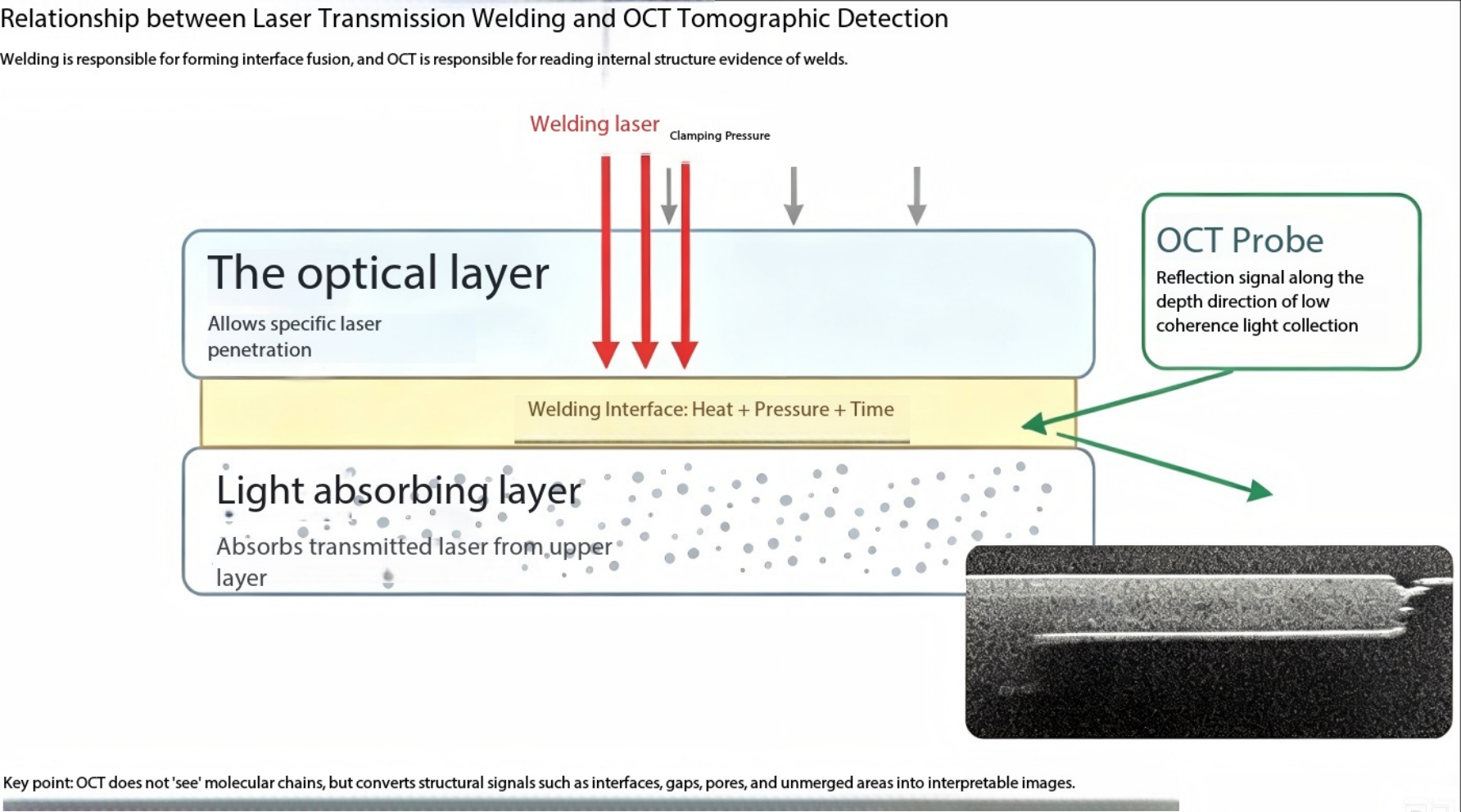
The core capabilities of OCT in plastic welding inspection:
Detection Dimension | OCT might-have-been | The limitations of traditional methods |
Interface fusion state | Show whether the original interface has disappeared | Air tightness testing can only determine whether there is a leak or not; tensile testing can only assess macroscopic strength. |
Internal Defect Identification | Detect bubbles, voids, incomplete penetration, abnormal collapse, etc. | Visual inspection can only detect surface collapse marks. |
Welding depth uniformity | Quantitative analysis throughout the entire circumference/area of the weld seam | Destructive sampling can only collect samples and cannot cover the entire length. |
Online comprehensive inspection capability | 100% online detection to identify individual abnormalities | The essence of the random inspection mechanism lies in its "probabilistic generation" approach. |
Key insight: The core principle of OCT inspection is not merely to "see more clearly," but rather, for the first time, provides a quantifiable answer to the question of whether the weld has been properly completed.
IV. Two Typical Patterns of Fake Welding
Mode 1: Planar overlay welding with simulated weld (colapsing type)
Typical scenario: a flat or surface-overlap welding structure with no interference fit, relying solely on instantaneous clamping by the fixture.
• The weld surface exhibits significant collapse and noticeable material overflow.
• Low-voltage short-term air tightness tests may be satisfactory, whereas high-pressure blasting results in direct leakage.
• The lateral (in-plane) tensile strength is not low, but the vertical anti-delamination strength is extremely low.
• After tearing, the interface appears nearly flat and layered, with abundant residual glass fibers visible under microscopy—indicating that the material matrix has not fused.
The essence of false welding: The surface plastic softens and flows, temporarily sealing minor leakage pathways, but no molecular-level interpenetration or entanglement occurs at the interface.
Mode 2: Circular interference ring joint pseudo-welding (mechanical interlocking type)
Typical scenario: A circumferential butt-welded structure where an interference fit provides continuous radial pre-tension.
• The joint surface is smooth with minimal collapse.
• The static drawing force value is excessively high—due to mechanical friction generated by an interference fit.
• Discrete punctate tear marks, with small amounts of substrate remaining on both sides of the fracture site;
• The leakage rate significantly increases after temperature cycling or prolonged pressure maintenance.
The essence of false welding: The mechanical interlock formed during interference fitting masks the reality of insufficient interface fusion. Such products "perform excellently" in static tests, but under alternating loads or temperature cycling, the interference locking force is first depleted before the scattered point-like fusion zones are torn apart.
Comparison of the Two False Welding Modes
Comparison Dimension | Flat surface soldering with false welding | Circular interference ring joint with simulated welding |
Structural pre-tension force | No assembly interference; only instantaneous clamping by the tooling. | The interference fit provides a continuous radial pre-tension force. |
Thermal forming appearance | Significant weld collapse is observed, accompanied by extensive softening of the base material and increased material overflow. | The surface is smooth with slight depression. |
Air tightness performance | Low-pressure short-term pressure maintenance is feasible, whereas high-pressure blasting leakage may occur. | The initial air tightness test is highly likely to be qualified; leakage occurs after temperature cycling or prolonged pressure maintenance. |
Traction Performance | The explosive strength is extremely low, with layered fragmentation occurring even under light pressure. | The static drawing value is too high (due to interference friction). |
Fracture morphology | The interface exhibits a smooth layered structure with minimal adhesion to the base material. Significant residual glass fiber is observed at the bonding interface. | Discrete punctate tears with minimal residual substrate on both sides. Significant residual glass fiber at the interface. |
failure mode | Uniform surface load (air pressure) directly expands the interface. | Alternating/persistent tension first consumes the interference fit, followed by tearing of the punctate fusion zone. |
Source of the core illusion | The surface-softened plastic temporarily seals the tiny leakage channels. | The interlocking force of interference-fitted machinery masks insufficient interface fusion. |
⚠ Critical Warning: The first mode is relatively easy to detect visually or through collapse monitoring; whereas the second mode, with axial pull-out force data even exceeding that of normal welds, is highly concealed and represents the most dangerous "quality trap" in industrial manufacturing.
V. Case Study on OCT Online Detection Verification
With the introduction of OCT-based online comprehensive inspection, both aforementioned types of false welding issues are detected at the production stage.
Taking the circular welded component PPA+GF40 as an example, comparative tests were conducted at different welding temperatures:
state | temperature condition | OCT detection result | Traction Performance |
Insufficient penetration | Original Assembly | The interface is clearly visible with no fusion marks. | Extremely low; can be removed manually |
| Approximately 220°C (within the Tm-Td range) | The interface shows clear signs of enlargement. | The transverse shear stress meets the requirements, and vertical detachment is minimal.
|
| ≥280°C (above Td) | Pore clusters and material degradation zones are visible. | Decreased, cross-sectional brittleness |
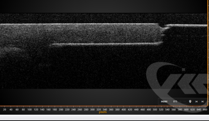
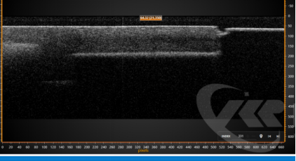 Normal welding
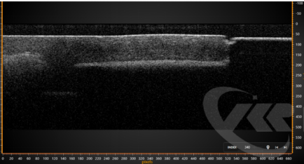 Degradation due to temperature rise
Key findings: Under both "220°" and "280° overtemperature" conditions, despite differing welding temperatures, OCT images consistently reveal the original interface between the upper and lower material layers—providing direct evidence of pseudo-welding.
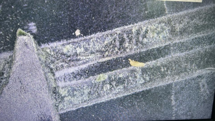
Microscopic verification: After destructive tearing of the planar weld specimen suspected to contain false welds, microscopic examination revealed extensive exposure of horizontal glass fibers with virtually no tear residues remaining on the base material, which closely matched the results obtained by OCT detection.
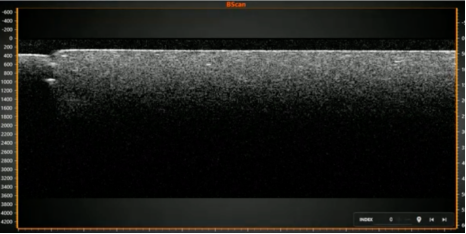
OCT scan image of the perfectly welded surface
(Figure 6 shows that after perfect welding is completed, the weld seam disappears entirely, and the upper and lower materials have fully fused into one piece.)
VI. A Systematic Solution to the Problem of Fake Welding
The value of OCT lies not only in "identifying issues" but also in providing a quantitative basis for process development. To systematically address false welding problems, a closed-loop approach must be established across the following dimensions:
1. Material Control – Eliminating potential risks at the source.
• Transmittance inspection of all weld seams: Ensure consistent transmittance across the welding area of upper transparent components to prevent insufficient heat transfer at the interface due to low transmittance.
• Fiber aggregation control: Implement batch management of glass fiber distribution on injection-molded parts and establish acceptable fiber aggregation levels.
• Moisture content control: PA materials must be dried to a moisture content <0.02% prior to welding to prevent water vapor bubbles from interfering with interfacial fusion during the welding process.
• Material welding performance evaluation: Preliminary quantitative tests are conducted on the type of glass fiber and its welding compatibility of the original material. Large-scale, systematic false welds occurring on the production line typically indicate this dimension as the primary cause.
2. Closed-loop process parameter control – Ensuring welding quality through four curves
False alarms often occur when parameters appear normal, making reliance solely on fixed power or time settings insufficient for detection. A four-curve coordinated closed-loop system must be established.
• Temperature curve: Ensure an appropriate heating rate, maintain the maximum temperature stable between Tm and Td, and allow sufficient interface plasticization and diffusion time.
• Collapsation volume curve: This distinguishes between "tolerance-induced collapse" and "effective plastic deformation-induced collapse"; the former occurs rapidly, while the latter exhibits a stable, gradual progression.
• Pressure curve: Pressure fluctuations should be controlled within ±5%, and sudden pressure spikes should be avoided during the plasticizing stage.
• Power curve: Power output should adaptively adjust during welding, rather than remaining fixed.
3. Comprehensive Online Inspection – From Random Sampling to Mandatory Inspection of Every Item
The OCT 100% online comprehensive inspection achieves structural-level quality assessment—not merely concluding that "this batch passes because the sampling test was successful," but rather documenting and evaluating the actual fusion status of each weld joint. This represents a qualitative leap: transitioning from statistical inference to individual verification.
As the industry consensus states: any weld without comprehensive structural-level inspection is essentially manufactured with inherent risks.
VII. Conclusion
The quality management system for laser plastic welding is evolving from "process parameter control" to "welding outcome control." The introduction of OCT technology does not merely add an enhancement but addresses a fundamental issue: it provides a quantifiable and online-verifiable answer for the first time regarding whether the weld has been successfully formed.
The danger of false welding lies not in its rarity, but rather in its considerable prevalence within certain material and structural combinations. Utilizing OCT for online tomographic inspection to address this quality gap provides a robust guarantee for achieving zero-defect high-quality component connections.
 Home
Home Products
 Telephone
 Message


